Design
Channel Map Designer
The DIB definition as a first-class artefact. Assign DUT pins, across sites, to tester channels — against the real tester configuration, not a spreadsheet convention — and save one plan that the schematic, the generated program and the DIB checker all read. One source; nothing to keep in sync by hand.
Overview
Every load board project answers the same question: which DUT pin lands on which tester channel, for each site? Traditionally that answer lives in an Excel sheet, checked after the fact by a vendor command-line tool. ATE·IQ makes it a native editor: pins down the rows, sites across, channels assigned against the instruments the tester configuration actually contains.
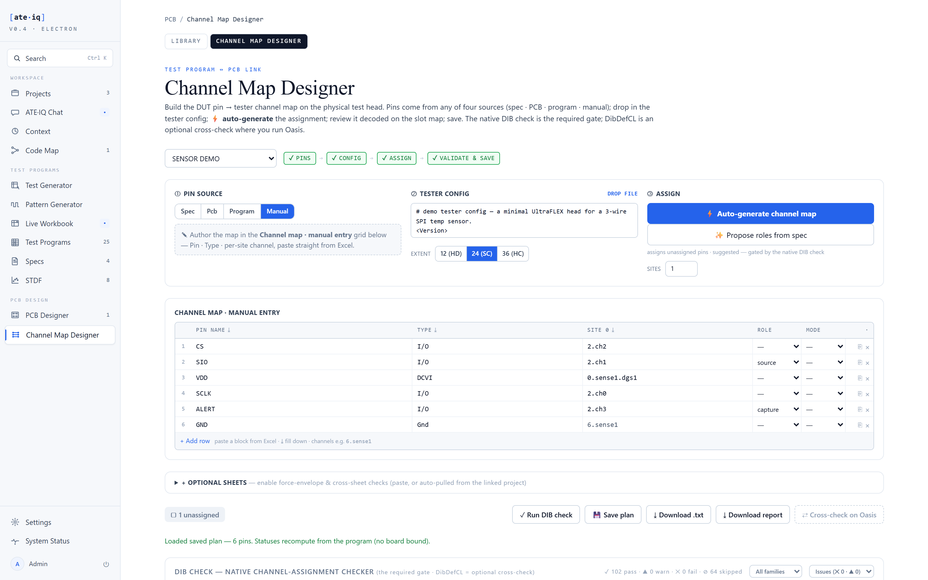
Assignment is type-aware. A digital pin offers digital channels; a power pin offers DCVI channels with force and sense; the auto-assign fills a board's worth of pins with channels of the right type, which you then adjust rather than type from zero. Pin metadata survives round-trips — a ground pin recorded with no channel stays a ground pin with no channel after save and reload, instead of being silently dropped as incomplete.
One saved plan, three consumers
The saved plan is authoritative. Three surfaces read it, and none of them keeps a private copy:
The schematic's channel flags come from the plan, so a drawing label cannot drift from the program. The generated IG-XL project's ChanMap matches the board's channels by construction, never by luck. All 166 rules run against the same plan the other two consumed — channel-type mismatches, capability violations, site-consistency errors.
How it works
Assignments are made against the tester's real configuration — actual slots and channels, not free text — with DUT pins and their types coming from the device profile. Type-aware auto-assign proposes channels of the correct instrument family for every pin, manual edits override any cell, and the 166-rule DIB checker runs offline — replacing the export-to-vendor-CLI round trip for day-to-day iteration — with findings in the editor and in the board's analysis hub. On save, the plan becomes the source for the schematic flags, the generated ChanMap and the DIB check, and pin metadata — including deliberate no-channel pins like grounds — round-trips intact.
Proven end to end
The demonstration plan maps the SPI pins onto UltraPin800 digital channels, VDD onto the DC-07 DCVI with separate force and sense, and the alert pin onto its own digital channel; GND is recorded as a ground pin with no channel, and stays that way across saves. Downstream, the 5-sheet schematic carries these channels as flags, the generated program's ChanMap matches them exactly, and the analysis hub's pin match reconciles board, plan and program without a manual crosswalk.