Generate
Pattern Generator
Configure a serial protocol and a transaction sequence; get cyclized IG-XL digital patterns and a live waveform. No hand-written vectors, and no gap between what the preview shows and what the pattern file contains.
Overview
Writing serial patterns by hand means transcribing a protocol's clocking rules into per-cycle pin states — mechanical work with mechanical failure modes. The Pattern Generator does the transcription from a declared protocol configuration, and labels every cycle with what it means.
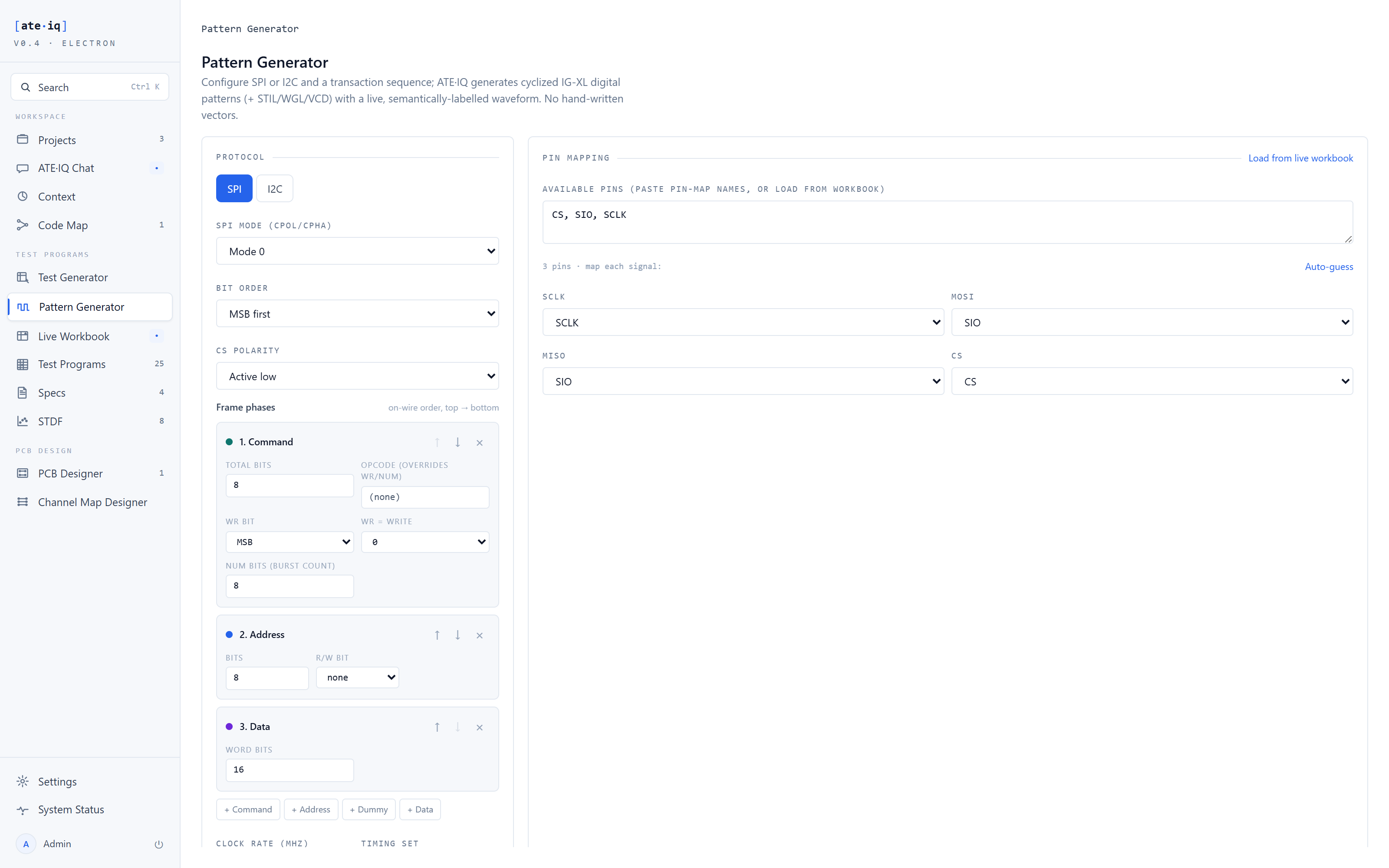
SPI covers all four CPOL/CPHA modes, MSB or LSB bit order, chip-select framing, MISO compare and masking, and a configurable frame — an ordered phase list of command, address, dummy and data phases, which is how real devices document their transactions. I2C covers START/STOP framing, 7- and 10-bit addressing, slave-ACK compare and the master NACK. Transactions support ranges and repeats; values enter as hex, decimal or binary.
One source of truth
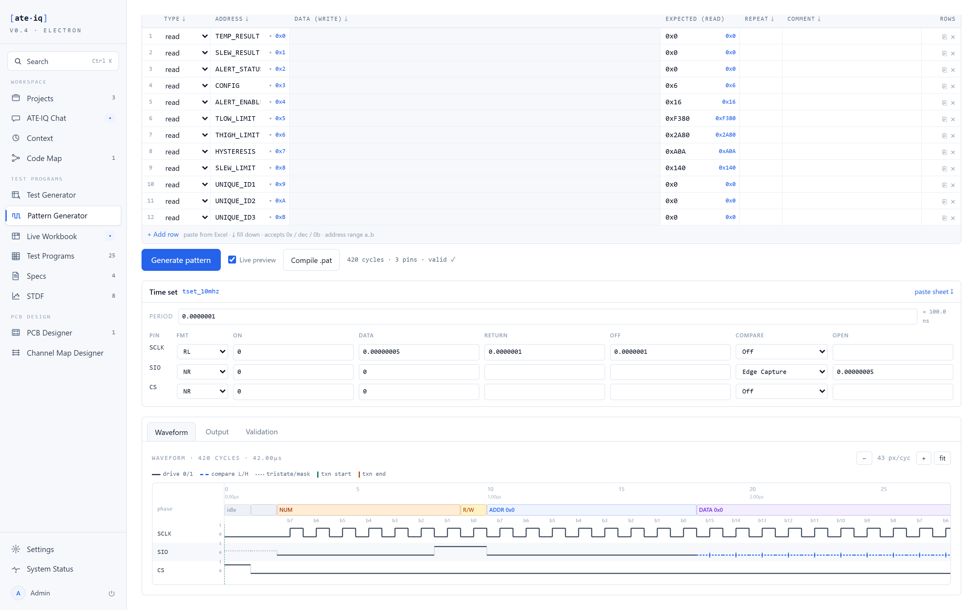
The waveform you inspect and the pattern the tester runs come from the same vectors — the preview cannot drift from the output.

Validators
Every configuration is checked before a single vector is emitted — a wrong setup fails loudly in the workspace, not at the tester.
From protocol to pattern
Pick a project — its saved bus profile, register map and generated patterns load automatically — or go standalone with a protocol choice and a pasted pin list. With a register map loaded, transactions are entered by register and field name, and whole test suites — reset-value reads, write/read-back — can be generated from the map in one click. The live waveform regenerates as you type, every cycle labelled with its phase and bit, so a wrong CPOL setting is visible as a wrong waveform rather than discovered at the tester. One generation emits all four formats from the same vectors: IG-XL ASCII for the tester, VCD, STIL and WGL for interchange.
Proven end to end
Selecting the demonstration project preloads the whole bench — the SPI protocol with its bidirectional SIO pin, the pin mapping, the frame phases, the register map and the transaction sequence — and the hero pattern from the generated test program opens in the viewer automatically. The 24 SPI patterns in that program were derived from the test requirements by the program generator, so the pattern an engineer inspects here is byte-for-byte the pattern the program runs.
IGXL_PATTERN_COMPILER); when none is present it reports
blocked rather than pretending the pattern compiled.